This post is part of a series relating to maker kits that I prepared for the HSBNE booth at Supanova 2016.
This kit will get you started with the Open Source Arduino micro-controller platform for co-ordinating sensors and actuators (e.g. LEDs and motors). This post steps you through building a series of simple circuits with a solderless breadboard, and loading example programs onto the Arduino micro-controller so you can explore working with some common components.
The circuits described here should also work with lots of other intro to Arduino kits e.g. Freetronics.
Kit Contents
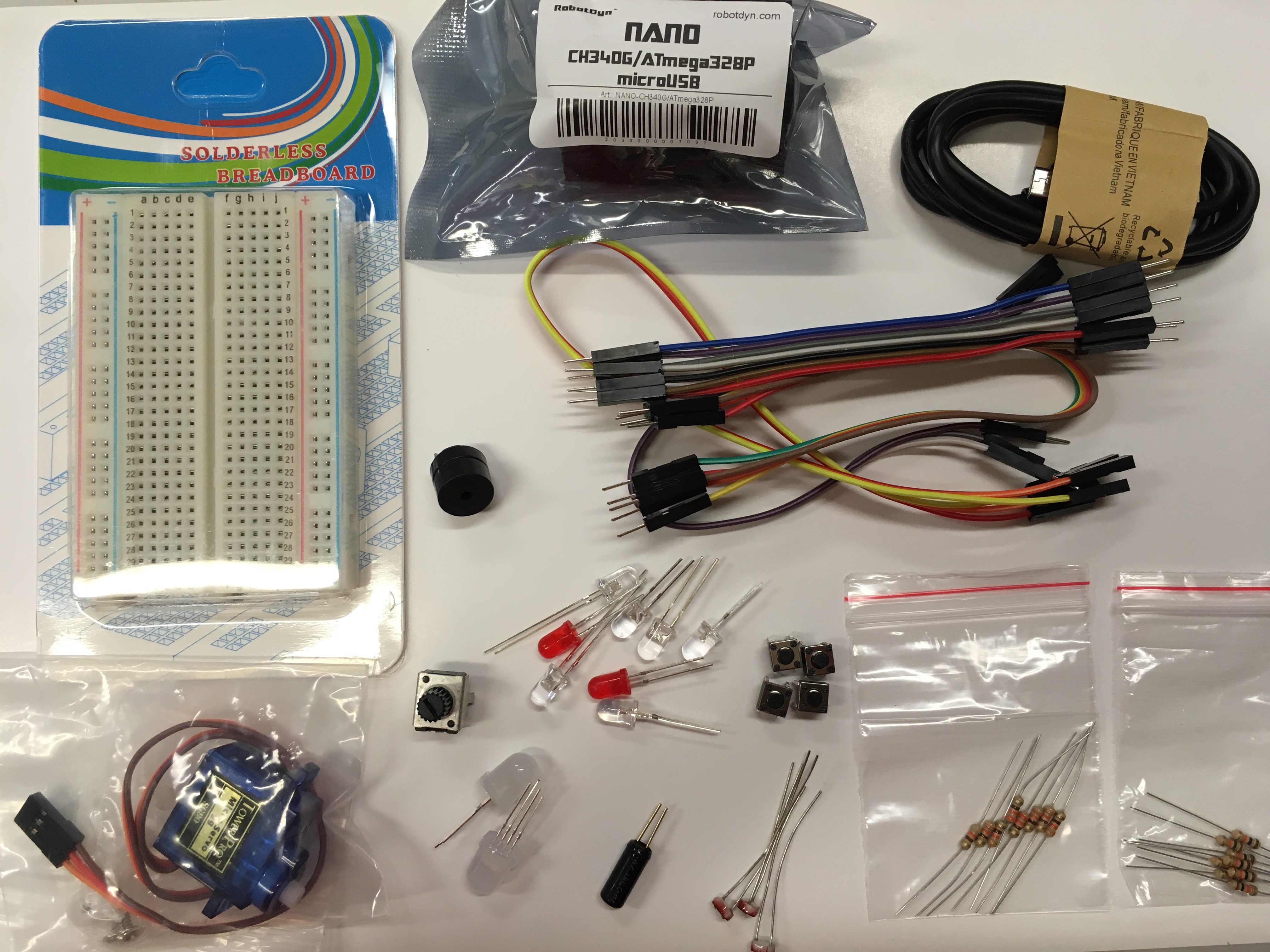
- Robotdyn Arduino nano
- solderless breadboard
- micro USB cable
- Jumper wires
- piezo buzzer
- servo
- 10K potentiometer
- assorted LEDs
- 4 x push buttons
- Neopixel LEDs
- tilt sensor
- 3 x light dependent resistors
- 330 ohm resistors
- 10K resistors
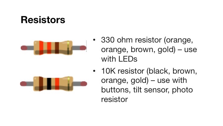
Resistors have stripes that you can use to identify their value:
Using the Arduino Nano
We're using a RobyDyn Arduino Nano. See the Arduino Nano reference page for details on the nano.
Key features:
- Arduino Nano ATMega328 16MHz
- Small, breadboard-friendly
- Has digital and analog GPIO (general purpose input / output) pins along the sides
- Power via micro USB port (e.g. use USB emergency phone charger / power pack) or supply 6 – 20V on pin VIN
Drivers
Before you can use the Nano, you'll need to install drivers on your PC or Mac. Install the CH341 USB-Serial Driver. You can download the driver from the links below:
You'll also need to install Arduino IDE
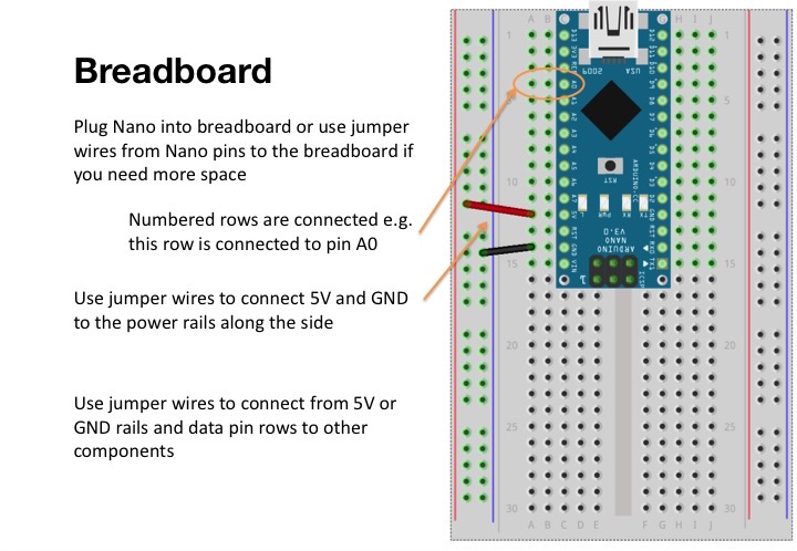
Breadboard
We'll use a solderless breadboard to build our circuits. You can use these to prototype circuits by pushing the component leads (i.e. legs) into the holes in the breadboard. Ours have power rails down the sides.
LED circuit
We'll start by blinking and fading an LED.
Building the circuit
LED stands for Light Emitting Diode. LEDs are polarized - they have a positive lead and a negative lead. You can think of them like a one-way valve, current can only flow through in one direction, and when you connect them the right way, they emit light. The longer lead is the anode (positive). We'll include a current limiting resistor in our circuit to avoid damaging the LED.

Grab your breadboard, Arduino nano and the following parts and build the circuit shown below:
- 5mm LED
- 330 Ohm resistor (orange-orange-brown)
- jumper wires
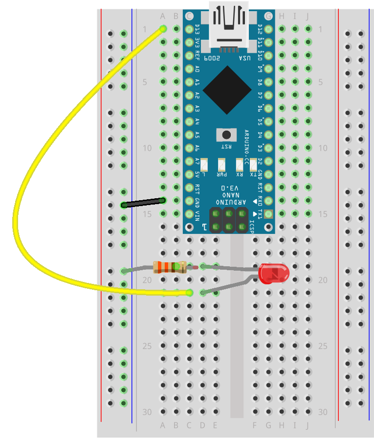
Use a jumper wire to connect the GND pin on the Nano to the negative power rail by pushing one end of the wire in to the hole next to GND, and the other in anywhere in the negative (blue) rail along the side of the breadboard. Use the 330 ohm connector to connect from the negative rail to another row on the breadboard, and push the short lead of the LED into that same row. The LED lead shown with the kink in it in the diagram is the positive, and it will connect via a jumper wire to digital pin 13 on the Arduino.
Uploading the code
We'll use Arduino Integrated Development Environment (IDE) to write and send programs to run on the Arduino. Make sure you have connected the Arduino to the computer via USB.
In Arduino IDE, open File > Examples > 01. Basics > Blink.
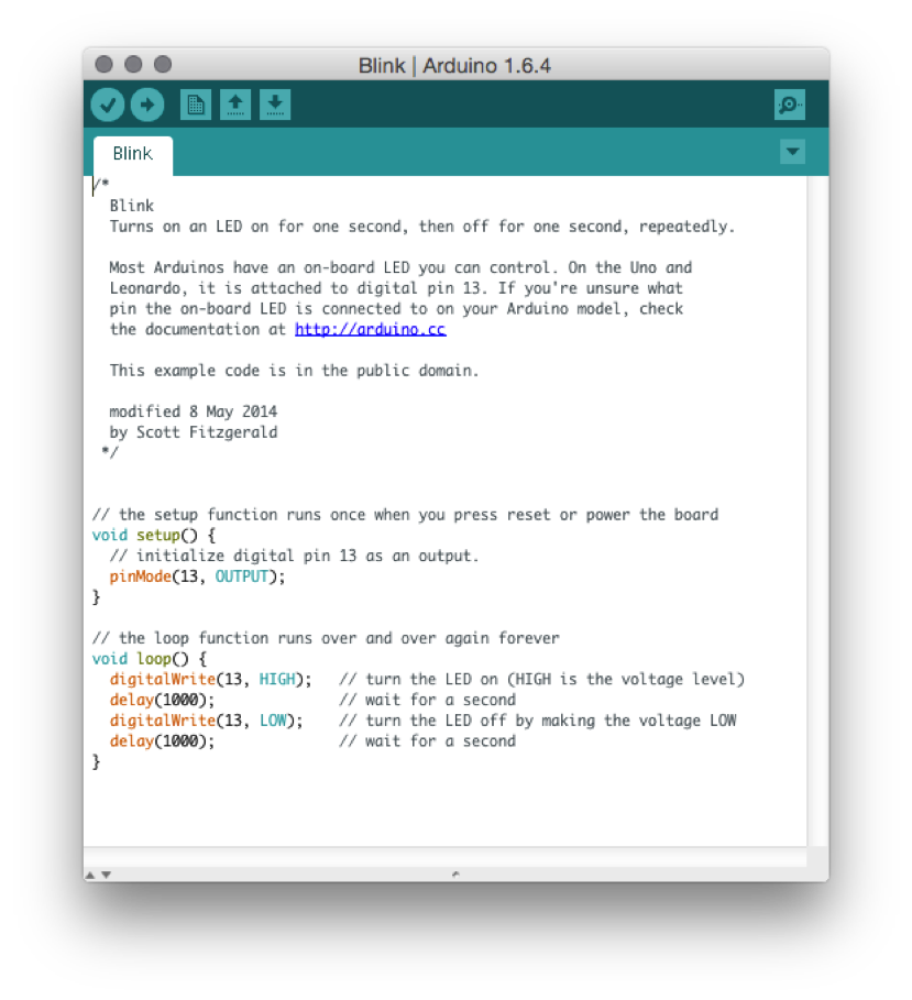
Blink uses the digitalWrite function to turn the LED on or off, by setting it to HIGH or LOW, with a delay (in milliseconds) in between. You can change this value and upload the code again to make it blink faster or slower. The on-board LED is also on pin 13 so you'll see it light up at the same time as the one in your breadboard. You can connect more LEDs to other pins in the same way - just make sure you have a 330 ohm current limiting resistor for each one.
Let's load the program onto the Arduino:
- In Arduino IDE, select the board by going to the menu: Tools > Board > Arduino Nano
- Then select the port Tools > Port > (the port for your board)
- Click on the Upload button (arrow pointing right) in the toolbar at the top of the Arduino code editor.
- Information and any problems are displayed in the console beneath the code editor
We can also use analogWrite to fade our LED. Switch the jumper wire that goes from the LED anode from pin 13 to pin 9 and then try
uploading this example:
File > Examples > 01. Basics > Fade
Having trouble with the LED not lighting up? Diodes are polarized - that means they will only work in one direction. If the on-board LED is lighting up but not the one in the breadboard, try turning it around the other way. Also check that you have selected the right resistor - if you use the 10K resistors the LED most likely won't light up.
Arduino Programming Primer
Here's a brief primer on the code you'll see in Arduino programs. Refer to https://www.arduino.cc/en/Reference/HomePage for more information on the language.
Comments
// This is a comment and will not be executed
// Applies to everything after the slashes until end of line
  /*
    Comments can also span several lines
    like this
  */
Variables
Variables store data. We often use them to store pin numbers or sensor readings. Here's an integer (whole number, no decimals) variable named led with initial value of 13
int led = 13;
A floating point (i.e. number with decimal places) variable named f with no initial value:
float f;
A constant variable does not change value after it has been set initially.
const int buttonPin = 2;
Functions
Every Arduino program has a setup and loop function:
void setup() {
  // runs once when Arduino is turned on or reset
}
void loop() {
  // runs after setup, repeats continuously
}
Statements
You can think of statements as steps in the program.
Each statement is ended by a semi colon (like putting a full stop at the end of a sentence). Here's an example of a statement - it's a function call that calls the delay function with an input parameter of 1000 milliseconds - the result of executing this statement is that the program will wait for 1 second.
delay(1000);
When we set the voltage of our pin to HIGH or LOW using digitalWrite that is also a statement:
digitalWrite(13, HIGH);
Button circuit
Let's try building another circuit, using an input component this time.
Building the circuit
Buttons are not polarized (i.e. they don't have a plus or minus) so you can plug them in either way. Our buttons have two sets of leads - one on each side, but you'll only need to connect one set for this circuit.
You'll need:
- jumper wires
- push button
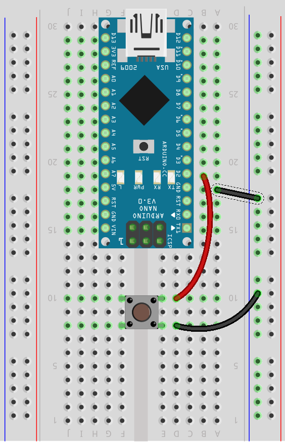
Connect one button lead to digital pin 2. Connect the other lead to GND.
Uploading the code
Open File > Examples > 02. Digital > DigitalInputPullup in Arduino IDE and upload to the Arduino. When you press the button, you should see the on-board LED light up.
This code sets the pinMode of the button pin to INPUT_PULLUP to enable a built-in resistor. The Arduino looks at the voltage on pin 2 and decides whether it is HIGH or LOW. If we didn't use this builtin resistor, when the button is not pressed, the voltage of the pin would float (sometimes causing errors), but we can solve this by using INPUT_PULLUP pin mode. The button reads HIGH when open and LOW when pressed. The code uses conditional statements (if / else statements) to trigger the LED to turn on or off. You can read more about pullup (to 5V) and pulldown (to GND) resistors here and here
void setup() {
  //start serial connection
  Serial.begin(9600);
  //configure pin2 as an input and enable the internal pull-up resistor
  pinMode(2, INPUT_PULLUP);
  pinMode(13, OUTPUT);

}

void loop() {
  //read the pushbutton value into a variable
  int sensorVal = digitalRead(2);
  //print out the value of the pushbutton
  Serial.println(sensorVal);

  // Keep in mind the pullup means the pushbutton's
  // logic is inverted. It goes HIGH when it's open,
  // and LOW when it's pressed. Turn on pin 13 when the
  // button's pressed, and off when it's not:
  if (sensorVal == HIGH) {
    digitalWrite(13, LOW);
  } else {
    digitalWrite(13, HIGH);
  }
}
Tilt sensor
The tilt sensor is pretty much interchangeable with the button - it is a digital sensor and is not polarized, but instead of pressing it, we tilt it to turn it on or off.
Building the circuit
For the button circuit we used a built-in pullup resistor. We can also add the resistor into the circuit ourselves. Here's an example of using a pulldown resistor.
You'll need:
- tilt sensor
- jumper wires
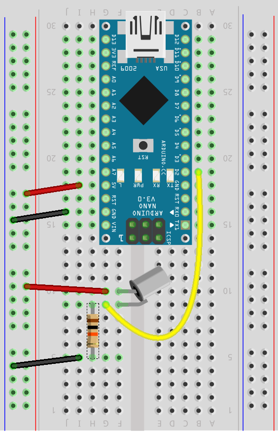
- 10K Ohm Resistor (brown-black-orange)
Connect the circuit. One lead of the tilt sensor is connected to 5V and the other is connected to pin 2. The 10K resistor connects the lead that is connected to pin 2 to ground with a 10K resistor in between.
Uploading the code
Open File > Examples > 02. Digital > Button
This code is similar to the previous example, but note that it uses INPUT for the pin mode (not INPUT_PULLUP). This means that our buttons and tilt sensor will read LOW when open and HIGH when triggered/pressed.
const int buttonPin = 2;     // the number of the pushbutton pin
const int ledPin =  13;      // the number of the LED pin

// variables will change:
int buttonState = 0;         // variable for reading the pushbutton status

void setup() {
  // initialize the LED pin as an output:
  pinMode(ledPin, OUTPUT);
  // initialize the pushbutton pin as an input:
  pinMode(buttonPin, INPUT);
}

void loop() {
  // read the state of the pushbutton value:
  buttonState = digitalRead(buttonPin);

  // check if the pushbutton is pressed.
  // if it is, the buttonState is HIGH:
  if (buttonState == HIGH) {
    // turn LED on:
    digitalWrite(ledPin, HIGH);
  } else {
    // turn LED off:
    digitalWrite(ledPin, LOW);
  }
}
Potentiometer circuit
So far we've worked only with the digital pins. Let's try connecting an analog sensor - we'll use the potentiometer (also known as variable resistor). The value changes when you turn the knob.
Building the circuit
You'll need:
- potentiometer
- jumper wires
The potentiometer has three pins.
Connect the middle pin to analog pin 0 (marked A0 on the nano). The other two pins can be connected either way - connect one side to ground and the other to 5V.
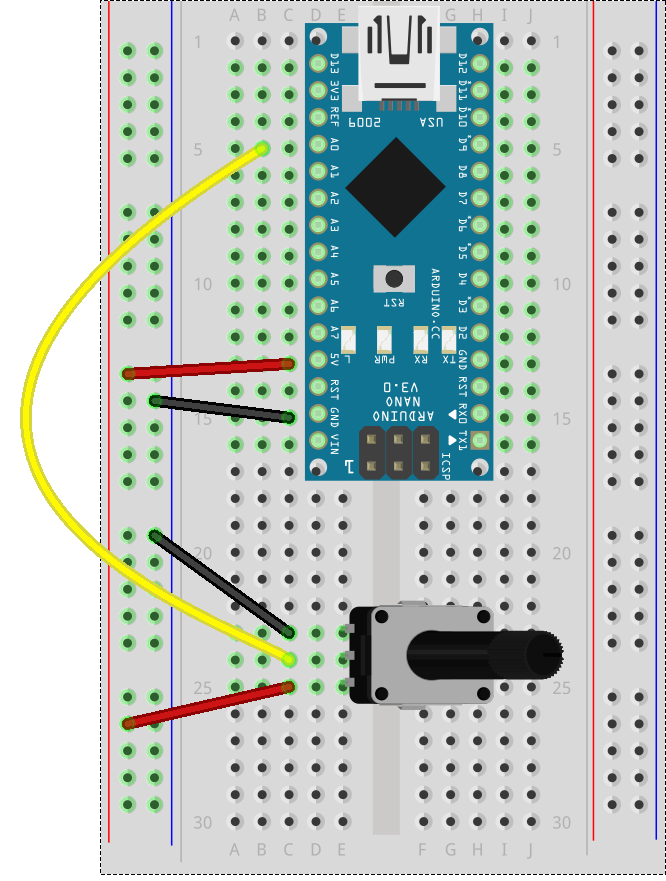
If you have trouble pushing the potentiometer into the breadboard, try taking some pliers and folding down the tabs on the bottom, as well as twisting the pins by 90 degrees - they seem to go into the breadboard better that way.
Uploading the code
Open File > Examples > 03.Analog > AnalogInput
When you twist the knob, you'll see the on-board LED blink slower or faster in response.
int sensorPin = A0;    // select the input pin for the potentiometer
int ledPin = 13;      // select the pin for the LED
int sensorValue = 0;  // variable to store the value coming from the sensor

void setup() {
  // declare the ledPin as an OUTPUT:
  pinMode(ledPin, OUTPUT);
}

void loop() {
  // read the value from the sensor:
  sensorValue = analogRead(sensorPin);
  // turn the ledPin on
  digitalWrite(ledPin, HIGH);
  // stop the program for <sensorValue> milliseconds:
  delay(sensorValue);
  // turn the ledPin off:
  digitalWrite(ledPin, LOW);
  // stop the program for for <sensorValue> milliseconds:
  delay(sensorValue);
}
Photo Resistor
Also known as LDR (light dependent resistor) or photocell, this analog sensor reads the ambient light level.
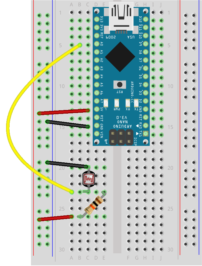
Building the circuit
Grab the following components from the kit:
- photo resistor
- 10K resistor (brown-black-orange)
- jumper wires
LDRs are non-polarized: connect one lead to ground. Connect the other lead to analog pin 0 (A0) and also the 10K resistor to 5V.
Uploading the code
Open File > Examples > 03.Analog > AnalogInput
This is the same code we used with the potentiometer, so if you already have it on the Arduino, you don't need to upload it again. Cover the photo resistor to block the light or shine a torch on it to see how it affects the blink rate of the on-board LED.
Servo Circuit
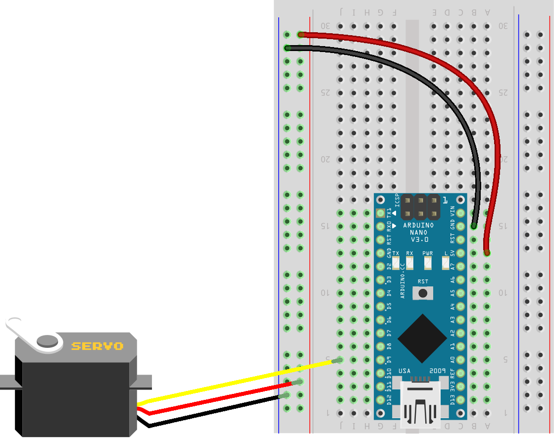
Building the circuit
You’ll need:
- servo
- jumper wires
Use jumper wires from the servo plug:
- Connect 5V (red) wire to 5V
- Connect GND (black or brown) wire to GND
- Connect signal (white or yellow) wire to pin 9
Uploading the code
Open File > Examples > Servo > Sweep to see the servo sweep from the maximum to minimum position (our servos sweep between 0 and 180 degrees).
We're importing a built-in library with #indlude <Servo.h> at the top of the program. The servo library uses a digital pin that supports Pulse Width Modulation (PWM - pins 3, 5, 6, 9, 10 and 11 on our nanos) to encode messages using pulses. Instead of on or off, a square wave is sent to simulate voltages between 0V (off) and 5V (on). Read more about PWM here.
#include <Servo.h>

Servo myservo;  // create servo object to control a servo
// twelve servo objects can be created on most boards

int pos = 0;    // variable to store the servo position

void setup() {
  myservo.attach(9);  // attaches the servo on pin 9 to the servo object
}

void loop() {
  for (pos = 0; pos <= 180; pos += 1) { // goes from 0 degrees to 180 degrees
    // in steps of 1 degree
    myservo.write(pos);              // tell servo to go to position in variable 'pos'
    delay(15);                       // waits 15ms for the servo to reach the position
  }
  for (pos = 180; pos >= 0; pos -= 1) { // goes from 180 degrees to 0 degrees
    myservo.write(pos);              // tell servo to go to position in variable 'pos'
    delay(15);                       // waits 15ms for the servo to reach the position
  }
}
This code uses a for loop to loop through each degree from 0 to 180 and set the servo position using servo.write(pos), then a second loop to go back again from 180 to 0. This is repeated indefinitely in the main loop function.
If you leave your potentiometer from the previous example plugged in to A0, you can try the sample program File > Examples > Servo > Knob to control the position of the servo using the potentiometer.
Neopixel Circuit
Neopixels are bright colorful LEDs that are individually addressable. They come in all different form factors - strips, rings, grids etc, and you can chain hundreds of them together and control them via just one single I/O pin on the Arduino.
*Technically our LEDs are called APA106 addressable LEDs but they are compatible with the Neopixel library, so we'll refer to them as neopixels from now on.
You'll need:
- 2 x neopixel LEDs
- jumper wires
- push button (optional for extension circuit)
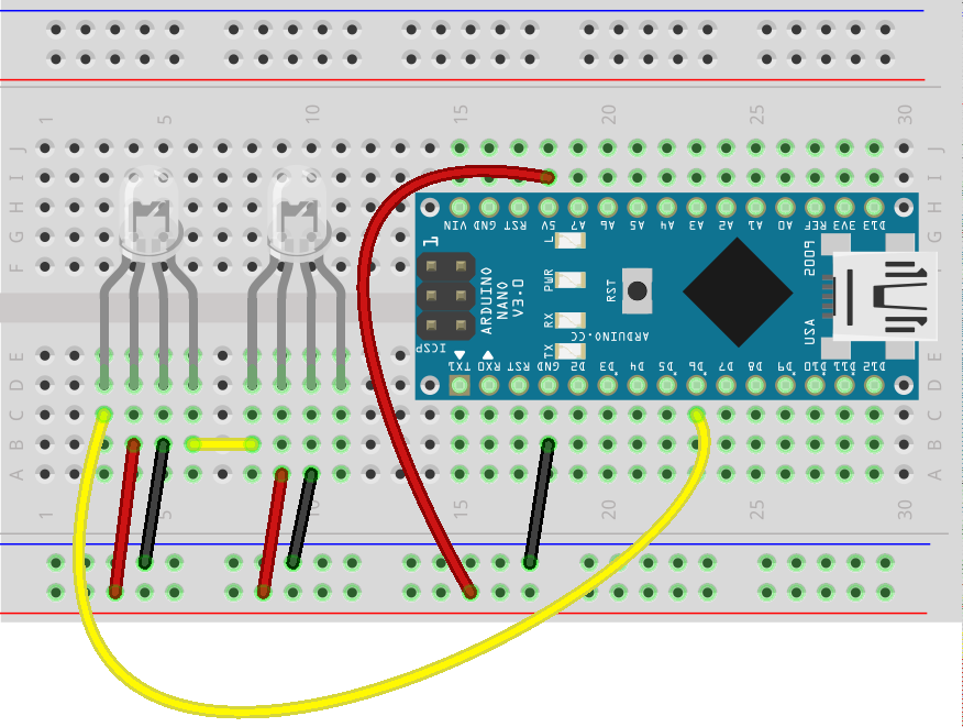
Each LED has four leads:
- data in
- 5V
- ground
- data out
The longest lead on our neopixel LEDs is the 5V lead, and in the diagram below, it is second from the left on each LED. To chain LEDs, connect data out to data in on the next LED. We'll attach our LEDs to pin 6.
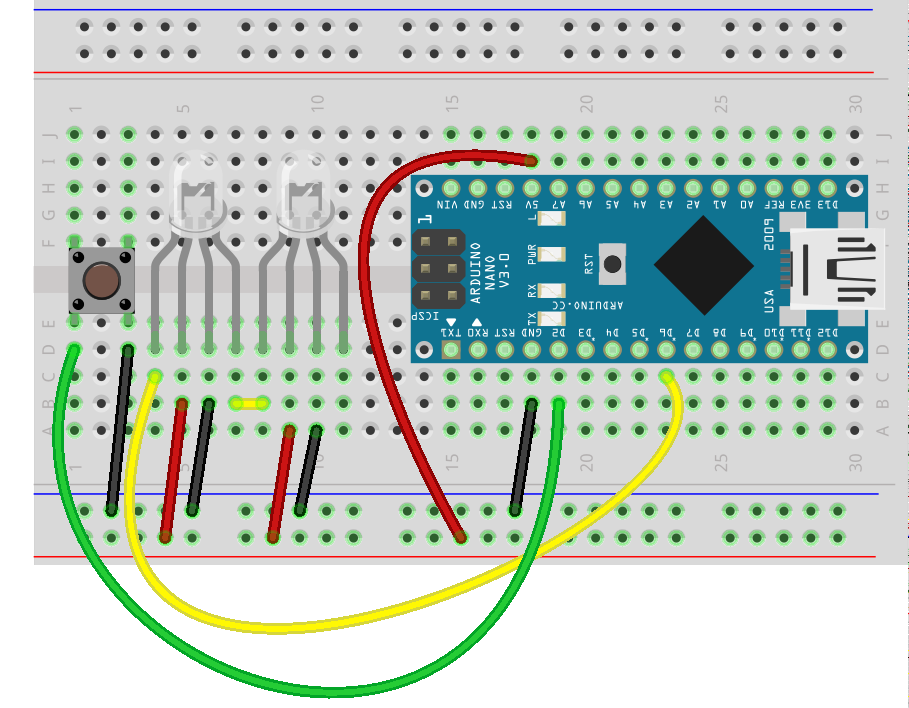
If you want to try controlling the pixels via button presses, also add a button on pin 2:
Uploading the code
We'll need to install a third party library to use the Neopixels. We're using the Adafruit Neopixel library.
In the Arduino IDE menu, go to Sketch > Include Library > Manage Libraries and then search for Neopixel
Click on Adafruit Neopixel and then on the Install button. When it is installed you'll see 'INSTALLED' next to the library name in the manager.
![]()
Close the manager and then open File > Examples > AdaFruit_Neopixel > simple
The code starts by including the library and setting up the pixels. We'll need to change it to use 2 pixels:
#include <Adafruit_NeoPixel.h>

#define PIN            6
// How many NeoPixels are attached to the Arduino?
#define NUMPIXELS      2
// When we setup the NeoPixel library, we tell it how many pixels, and which pin to use to send signals.
// Note that for older NeoPixel strips you might need to change the third parameter--see the strandtest
// example for more information on possible values.
Adafruit_NeoPixel pixels = Adafruit_NeoPixel(NUMPIXELS, PIN, NEO_GRB + NEO_KHZ800);
The first parameter is the number of LEDs we have chained together i.e. 2. The second parameter is the pin that the pixels are connected to (i.e. pin 6). The last input parameter controls the color order & frequency and we can usually leave it as is, but you can experiment with the different options (NEORGB + NEOKHZ400) if you are using a different type of neopixel. The LEDs are numbered from 0 onwards - so for two LEDs it will be LED 0 and LED 1.
In our set up we need to initialize the pixels:
void setup() {
  pixels.begin();
}
We can control the color of each LED with setPixelColor(pixel, color) and then follow with pixels.show() to make it live. Color takes red, green and blue values (between 0 – 255 for each one). e.g. set the first neopixel (pixel 0) to red:
pixels.setPixelColor(0, pixels.Color(255, 0, 0));
pixels.show();
Simplified example that turns the LEDs green:
#include <Adafruit_NeoPixel.h>
#define PIN            6
#define NUMPIXELS      2
Adafruit_NeoPixel pixels = Adafruit_NeoPixel(NUMPIXELS, PIN, NEO_GRB + NEO_KHZ800);

void setup() {
  pixels.begin();
}

void loop() {
  for(int i=0;i<NUMPIXELS;i++){
    pixels.setPixelColor(i, pixels.Color(0,150,0));
    pixels.show();
    delay(500);
  }
}
Try adding a button and uploading File > Examples > AdaFruit_Neopixel > buttoncycler to cycle through different behaviour each time you press the button.
Piezo Circuit
We can use a piezo buzzer to make beeps and music (of a sort). It's the same component you'll find in musical birthday cards and toys. It often sounds better if you tape it to a box or piece of card to amplify the sound.
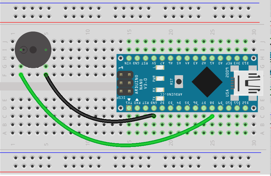
Building the circuit
You'll need:
- piezo buzzer
- jumper wires
The piezo is polarized so make sure you check for the small + on the top to get it the right way around. Connect the positive lead to pin 8 and the negative lead to ground.
Uploading the code
Open File > Examples > 02. Digital > toneMelody and upload to the Arduino. All of the code is in setup so it will only play the melody once. If you want to hear it again, you can press the reset button to restart the program.
This code uses an array (list of values) to keep track of the pitches and durations for the notes of the melody and then loops through those lists to play the song using the builtin tone function. The pitch values are constants from pitches.h, which should show up as a separate tab in the Arduino IDE editor.
For example, noteDurations is a list of integer values:
int noteDurations[] = {
  4, 8, 8, 4, 4, 4, 4, 4
};
You access a value in the list by position in the list (starting at 0) e.g. nodeDurations has values from 0 - 7.
noteDurations[0]is 4noteDurations[2]is 8noteDurations[8]will cause an error (outside the range of values)notesDurations[thisNote]uses the thisNote variable from the for loop, which will start at 0 and step through the values in the array each time through the loop until it reaches the end (7).
#include "pitches.h"

// notes in the melody:
int melody[] = {
  NOTE_C4, NOTE_G3, NOTE_G3, NOTE_A3, NOTE_G3, 0, NOTE_B3, NOTE_C4
};

// note durations: 4 = quarter note, 8 = eighth note, etc.:
int noteDurations[] = {
  4, 8, 8, 4, 4, 4, 4, 4
};

void setup() {
  // iterate over the notes of the melody:
  for (int thisNote = 0; thisNote < 8; thisNote++) {

    // to calculate the note duration, take one second
    // divided by the note type.
    //e.g. quarter note = 1000 / 4, eighth note = 1000/8, etc.
    int noteDuration = 1000 / noteDurations[thisNote];
    tone(8, melody[thisNote], noteDuration);

    // to distinguish the notes, set a minimum time between them.
    // the note's duration + 30% seems to work well:
    int pauseBetweenNotes = noteDuration * 1.30;
    delay(pauseBetweenNotes);
    // stop the tone playing:
    noTone(8);
  }
}

void loop() {
  // no need to repeat the melody.
}
Light theremin
Here's a circuit that combines sensors and actuators. We'll build a noise maker that responds to light.
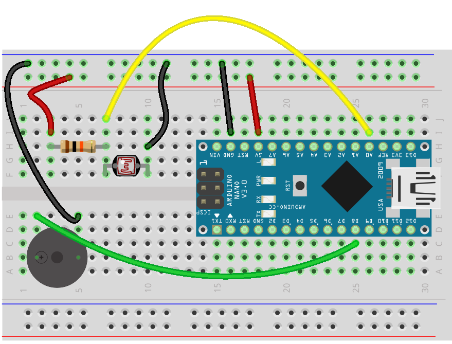
Building the circuit
You'll need:
- photo resistor
- piezo buzzer
- 10K resistor (brown-black-orange)
- jumper wires
Connect the photo resistor to A0. Connect the Piezo buzzer to pin 8.
Uploading the code
Open File > Examples > 10.StarterKit > p06_LightTheremin
The buzzer will start making noise as soon as you finish uploading the code. Shine a light on the photo resistor (or cover with your hand) and you'll hear the noises change in response.
Keyboard
Here's another fun project you can build with your kit: a musical keyboard using buttons and resistors.
Building the circuit
You'll need:
- 4 x push buttons
- piezo buzzer
- 330 Ohm resistor
- 5 x 10K resistors
- jumper wires
Here's the circuit.
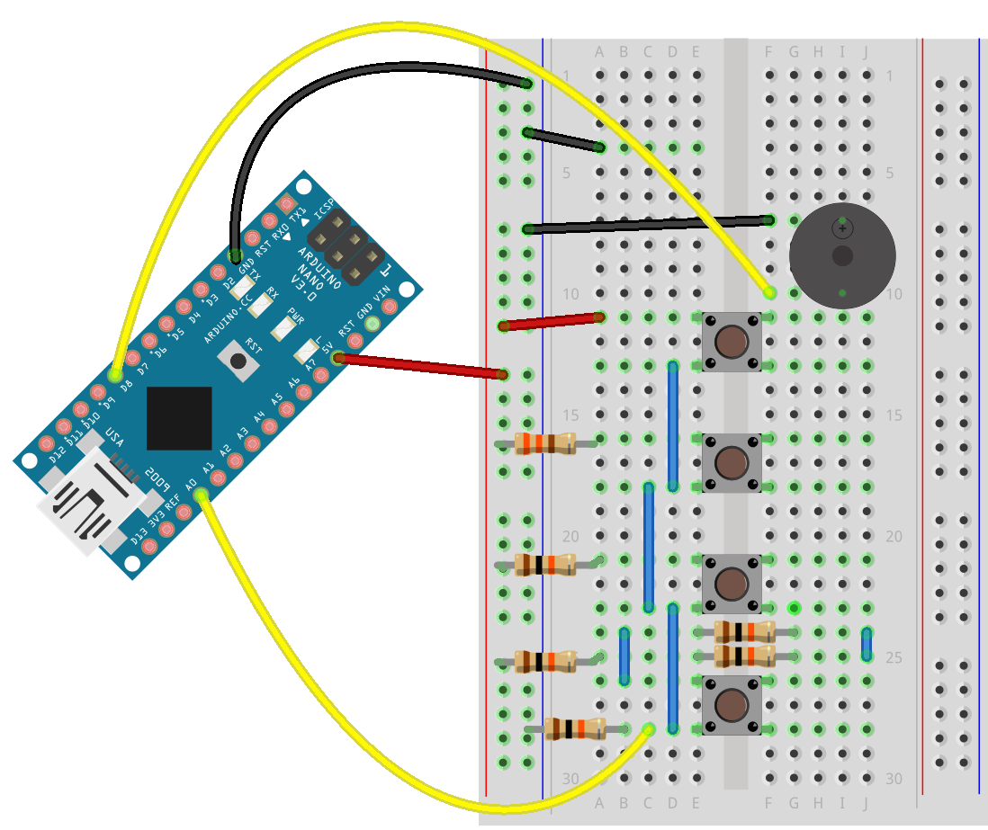
There's a piezo on pin 8, and the buttons with resistors all connect via A0.
Note that the top resistor is a 330 ohm resistor while all of the others are 10K. It's a bit of a squeeze trying to fit everything on the one breadboard, so for this circuit you might want to use jumper wires directly from the nano pins - use the jumpers with the sockets on the nano and plug regular jumper wires with pins on the ends into the other end to extend them as necessary.
Uploading the code
You can find the code for this circuit in File > Examples > 10.StarterKit > p07_Keyboard
Press the buttons to play different notes.
Next steps
These circuits should get you started with the basics of reading and writing to analog and digital components.
For more basic circuits and information, try the following links:
I also recommend this comprehensive book: Arduino Workshop by John Boxall of TronixLabs in Melbourne (TronixLabs is also a great place to find parts and other kits).
You can visit your local makerspace, e.g. HSBNE open nights on Tuesday nights every week, or come along to the Hack the Evening meetup group at the Fabrication Lab at The Edge on Thursday or Saturday nights to meet fellow makers and seek advice or inspiration for more advanced projects.