This post is part of a series relating to maker kits that I prepared for the HSBNE booth at Supanova 2016.
If you are looking for a way to add some colourful lighting to a costume, this kit will get your started. It includes a colorful individually addressable RGB LED neopixel ring, USB power pack and digispark micro-controller for programming the pixels.
Kit Contents
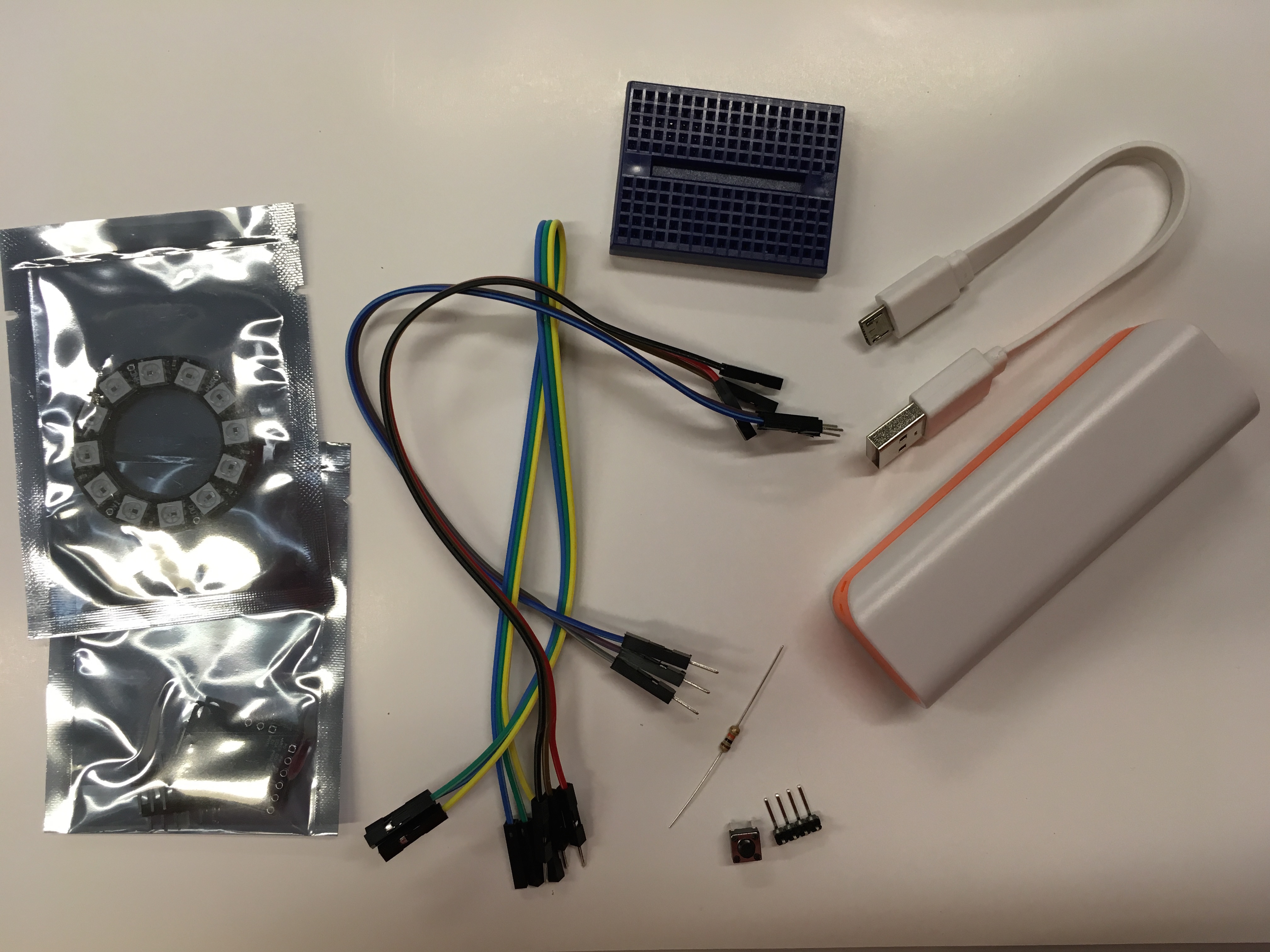
- 12 LED (neopixel) ring
- Digispark micro-controller
- Jumper wires
- mini breadboard
- pushbutton
- 10K resistor
- header pins
- USB battery pack
Neopixels
Neopixels (also known as WS2812B addressable LEDs) are chainable, individually addressable RGB (red, green, blue) LEDs that you can program to display a range of colors and patterns.
Neopixels come in many different forms - individual pixels, rings, bars, grids, strips etc. Each unit is connected via 5V, GND and a data pin, and needs to be controlled by a microcontroller.
See Adafruit's Neopixel uberguide for more information on neopixels.
Building the circuit
The kit includes a rechargeable USB power pack for powering your digispark and LEDs when you install them in a costume or prop. Use the included micro USB cable to charge it before you use it the first time.
The kit includes a solderless breadboard that you can use for prototyping but you'll probably want to solder some pins or wires onto your neopixel ring too. You can visit your local makerspace (e.g. HSBNE on a Tuesday night) if you don't have access to a soldering iron or need some advice for putting the circuits together.
Snap the right angle header pins into individual pins and solder onto the neopixel ring - you'll want a pin on data in, ground and the voltage in pin. You can also solder a pin onto data out if you want to chain multiple rings together.
![]()
Connect the 5V pin on the digispark to the 5V power pin on the neopixel ring. Also connect the GND pins. Finally, connect the data input pin on the neopixel ring to a digital pin on the digispark (e.g. pin D1).
![]()
You can solder header pins onto the digispark if you want to use the breadboard or to connect with jumper wires directly. If you need to be able to fit it into a small space (like in a prop), you might want to solder wires on directly. If this is the case, you might want to use alligator test leads (which you can find in electronics stores) for testing your circuit rather than the breadboard.
Add a button on pin D2 if you want to be able to trigger different patterns or colors by pressing the button. We use a 10K pullup resistor to help prevent floating values that can result in errors when reading from the button pin.
![]()
Digispark microcontroller
We're using digispark microcontrollers to control the LEDs. These are not quite as powerful as an Arduino, but are smaller and are a great choice for controlling LED lights for costuming and props.
We'll program the digispark using Arduino IDE, so you'll need to install Arduino IDE - at least version 1.6.7 or later.
You can find detailed instructions on getting set up to program the digispark board here. Note: if you are on Windows you'll need to install the drivers from that link before you do anything else.
The first time we go to use the Digispark, we'll need to make sure we have the board support installed.
In Arduino IDE, Open File > Preferences
Edit the boards manager URL field to add:
http://digistump.com/package_digistump_index.json
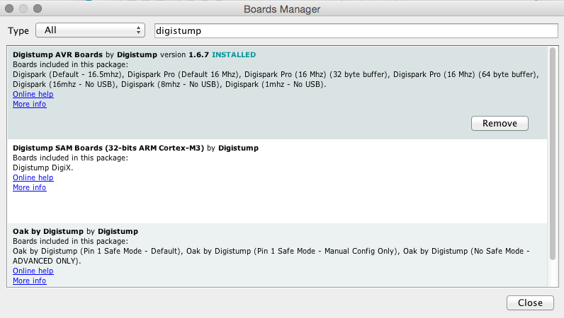
Save the preferences then in the menus, go to Tools > Board > Board Manager. Search for Digistump, and select and install the Digistump AVR boards extension, then close the manager.
Now go to the Tools > Board menu and select the Digispark (Default - 16.5mhz) option. You don't need to select a port.
When you go to upload a program, leave the digispark unplugged. The IDE will prompt you when to plug the board in to the USB port.
Note: the USB cable provided with the kit is for charging the battery pack and powering the digispark but it isn't suitable for data transfer. You will need to use your own micro USB cable (e.g. from a phone, camera or other device) to do the programming.
Code
We'll need to install a third party library to use the Neopixels. We're using the Adafruit Neopixel library.
In the Arduino IDE menu, go to Sketch > Include Library > Manage Libraries and then search for Neopixel
Click on Adafruit Neopixel and then on the Install button. When it is installed you'll see 'INSTALLED' next to the library name in the manager.
![]()
Close the manager and then open File > Examples > AdaFruit_Neopixel > strandtest
The code starts by including the library and setting up the pixels (comments have been removed for brevity). We'll need to change it to use 12 pixels and pin 1.
#include <Adafruit_NeoPixel.h>

#define PIN 1

Adafruit_NeoPixel strip = Adafruit_NeoPixel(12, PIN, NEO_GRB + NEO_KHZ800);
The first parameter is the number of LEDs we have in the ring i.e. 12. The second parameter is the pin that the pixels are connected to (i.e. pin D1). The LEDs in the ring are numbered from 0 onwards - i.e. 0 to 11.
In our set up we need to initialize the ring:
void setup() {
  strip.begin();
}
We can control the color of each LED with strip.setPixelColor(pixel, color) and then follow with strip.show() to make it live. Color takes red, green and blue values (between 0 – 255 for each one). e.g. set the first neopixel (pixel 0) to red:
strip.setPixelColor(0, strip.Color(255, 0, 0));
strip.show();
If you would like to use the button, open File > Examples > AdaFruit_Neopixel > buttoncycler to cycle through different behaviour each time you press the button. Don't forget to change the pixel numbers and pin values to match your circuit:
#define BUTTON_PIN   2

#define PIXEL_PIN    1

#define PIXEL_COUNT 12
The pixels are off to begin with by default with the buttoncycler program, so you'll need to press the button to start the show.
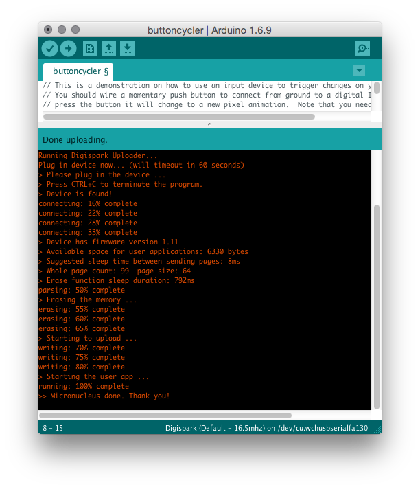
Hit the upload button in the Arduino IDE toolbar to send the program to the digispark. You'll be prompted to plug the digispark into the USB and then you should see some progress messages and finally 'Micronucleus done'.
If it times out, make sure you have the drivers installed, and then try using a different USB port or a higher quality micro USB cable (the one in the kit is not suitable for programming - it is designed for charging/power only). If it still doesn't work, you might need to unplug your components from the digispark and try programming the bare board (if you have a short or some other problem with your circuit it will prevent the code from being able to be loaded).
Next steps
You can add other components to expand the capabilities of your circuits e.g. add an accelerometer for lights triggered by movement, or add a PIR sensor to sense nearby motion. You can use this microcontroller to control other types of neopixels - you might like to try strips, or individual pixels joined by wire or conductive thread. If you are connecting a lot of pixels (e.g. more than 16) you'll probably want to add a second battery pack, one just for the pixels and one for the microcontroller.
To learn more about programming with Arduino, take a look at Adafruit's Neopixel projects, or the Arduino Playground.