I've been using Digispark for wearable projects lately because of its small size and low cost. The clones I've been using have a built-in MicroUSB port which is convenient for both programming and powering the boards.
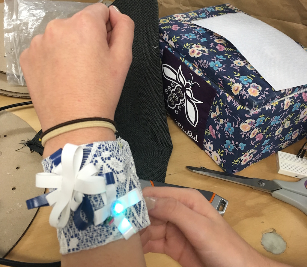
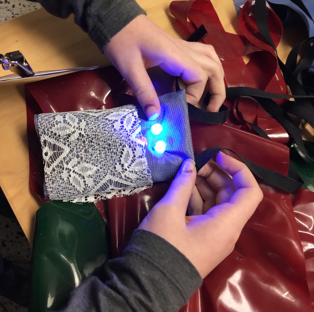
I had the opportunity to facilitate a visual arts workshop using these boards with high school students through Flying Arts Alliance's ArtizDIGITAL@TheEdgeSLQ. Some of the students' wearable projects in the process of being made:
Electronics
We used 8mm through-hole APA106 RGB addressable LEDs and individual WS2812B LEDs, which both use the same protocol and which are commonly referred to as Neopixels, as well as push buttons and photo resistors.
We soldered MicroUSB plugs onto 3 x AA battery holders to power the boards via the USB port. Here's a guide to the USB port pinout .
Here are some example circuits for getting started with Digisparks. First, install the Digispark board into Arduino IDE via Boards Manager as described here.
Photo Resistor
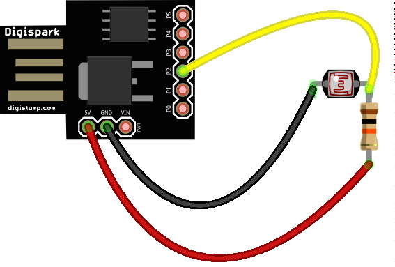
Attach the photo resistor to pin P2 with a 10K resistor to 5V. In the code we'll need to identify this as pin 1 (because P2 is actually analog port 1). Using analog pins with Digispark is a bit confusing but P3 is 3, P4 is 2 and P5 is 0 in the code.
To test this circuit, Open File > Examples > 03.Analog > AnalogInput in Arduino IDE and change the sensor pin to 1 and the LED pin to 1 (or 0 depending on your Digispark).
- Select board (Digispark Default 16.5 Mhz) from the Tools menu
- Make sure Digispark is unplugged
- Click on 'Upload'
- Plug in the Digispark when prompted (watch the messages at the bottom of the editor window)
You'll see the rate that the on-board LED blinks changes as the light level changes (try waving your finger near the photo resistor or shining a light over it).
Neopixels
![]() Solder wires from the Digispark to the Neopixels. Alternatively you can use IC hooks for prototyping. The pin order for the through-hole LEDs we used is: DIN, 5V, GND (longest pin) and DOUT.
Solder wires from the Digispark to the Neopixels. Alternatively you can use IC hooks for prototyping. The pin order for the through-hole LEDs we used is: DIN, 5V, GND (longest pin) and DOUT.
Install the AdaFruit Neopixel library in Arduino by downloading the zip file, unzipping and copying into your Arduino libraries folder (e.g. in ~/Documents/Arduino/libraries on Mac)
Restart Arduino IDE and then open File > Examples > AdaFruit Neopixel > strandtest
Change the code so that the pin number is 1 and the pixel count is 2 to match our circuit
The Neopixels should now cycle through some different colors and patterns. Because P1 is also connected to the on-board LED, we'll see it blinking too. If this bothers you, use a different I/O pin.
Adding a Button
![]()
Attach a button to P0 with a 10K pull down resistor. Open File > Examples > AdaFruit Neopixel > buttoncyler to test and change the pins for the pixel strip and button to 1 and 0.
Now you can combine the photo resistor and neopixel button circuits, and have fun coding light-reactive neopixels for your next wearables project!