These were my notes from the Espruino on ESP8266 Wearables session at CampJS in November 2015, republished from my gist.
In this session, we made "blinged up bowties", because bowties are cool.
Getting set up
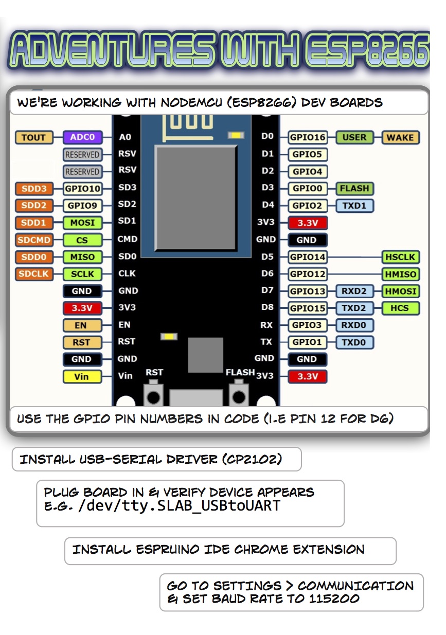
The boards are flashed with Espruino. Install the CP2102 driver and Espruino IDE from the Chrome extensions store. See my Getting Started with Espruino post for more details.
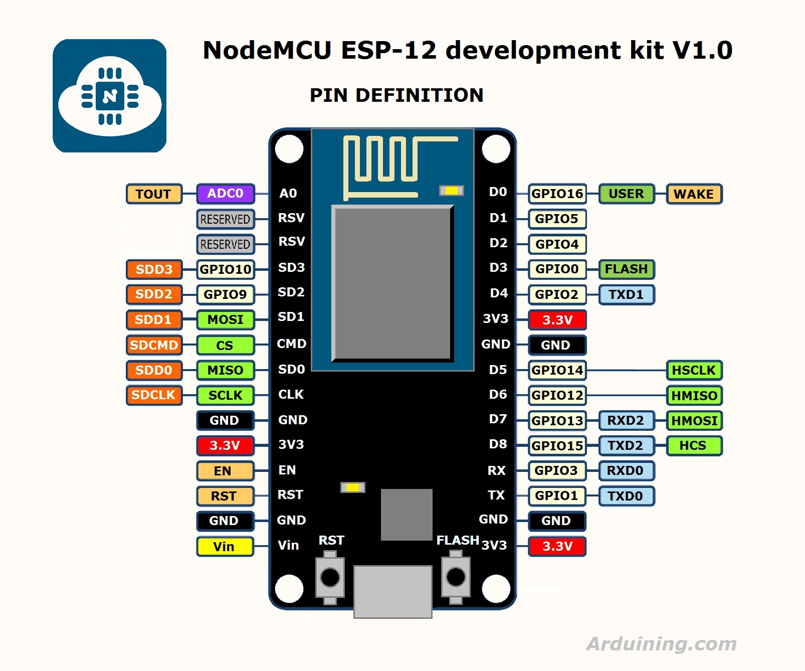
We are using the GPIO pin numbers in the code e.g. pin 4 not D2.
Blink
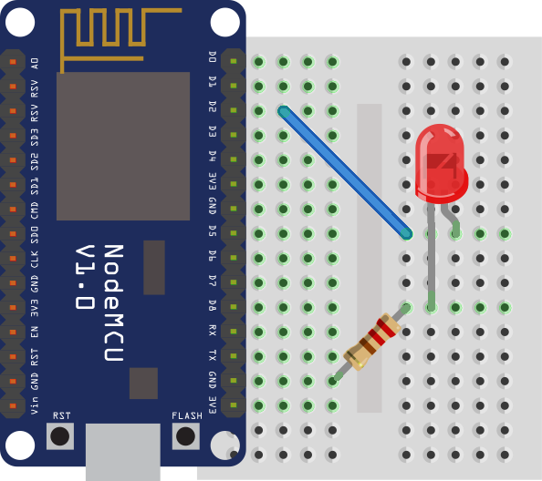
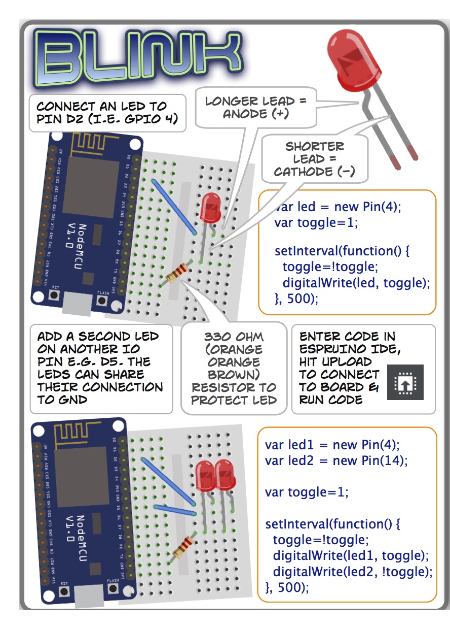
Connect LED to pin D2 (i.e. GPIO4). The longer lead is the positive (anode) lead, which connects to D2. The shorter lead (cathode) connects with a 330 ohm resistor (orange orange brown) to ground.
var led = new Pin(4);
var toggle=1;

setInterval(function() {
  toggle=!toggle;
  digitalWrite(led, toggle);
}, 500);
Enter the code in Espruino IDE, and hit upload to connect to the board and run the code.
Add a second LED:
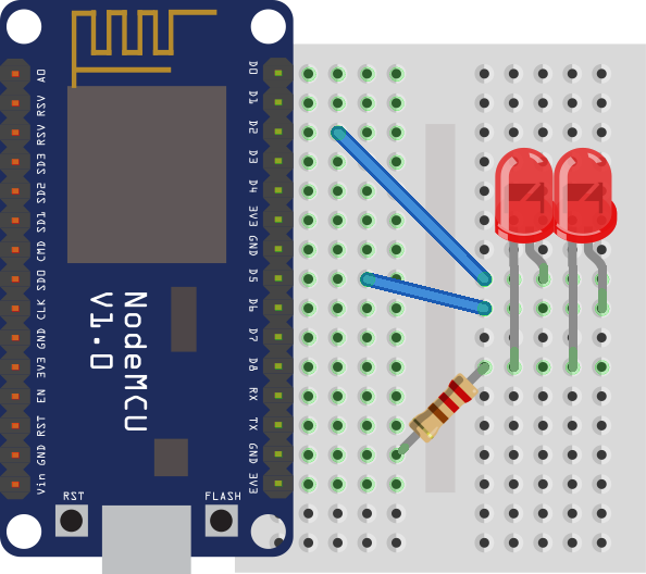
var led1 = new Pin(4);  // marked D2
var led2 = new Pin(14); //marked D5

var toggle=1;

setInterval(function() {
toggle=!toggle;
  digitalWrite(led1, toggle);
  digitalWrite(led2, !toggle);
}, 500);
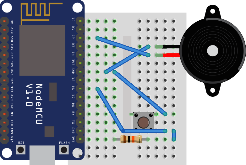
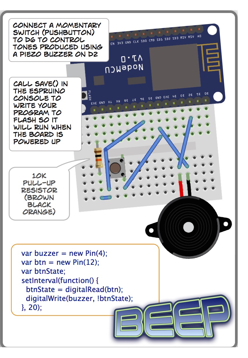
Button and Piezo
Connect buzzer to Pin D2. Connect button to pin D6.
var buzzer = new Pin(4);
var btn = new Pin(12);


setInterval(function() {
  digitalWrite(buzzer, !digitalRead(btn));
}, 20);
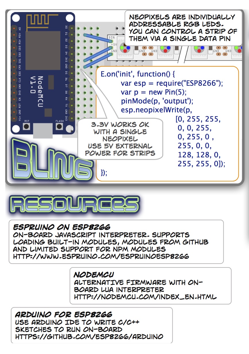
Neopixel
Neopixels are individually controllable RGB LEDs (WS2812b). Solder the 3 pin header on to the 5V/DIN/GND pins on the neopixel and then use hot glue to secure. Connect neopixel to pin D1.
![]()
  var esp = require("ESP8266");
  esp.logDebug(false);
  var pixel = new Pin(5);
  pinMode(pixel, 'output');
  esp.neopixelWrite(pixel, [0, 255, 255]);
The array of ints are values for Green, Red, Blue. If you are working with more than one neopixel you can chain them by connecting DOUT to DIN of next pixel, or use a ring or bar. In this case add more ints to the array (3 for each pixel) e.g. chain of three pixels:
esp.neopixelWrite(p, [0, 255, 255, 0, 0, 255, 0,255,0]);
Try some different colors e.g.
- orange 128,255,0
- purple 0, 255, 255
- blue 0, 0, 255
- hot pink 0,255,64
- forest green 255,0,128
Wifi
Require the wifi module to connect to a wireless network. You can run a basic web server on the board:
var wifi = require("wifi");
var ESP8266 = require("ESP8266");
var http = require("http");
var pixel = new Pin(13);
var purple = [0, 255, 255];
var red = [0,255,64];
var orange = [128,255,0];

wifi.scan(function(e,i){
  // print access points
  console.log(i);
});
wifi.connect("campjs-slow", "", null, function(err, ipInfo){
  if (err) {
    console.log(err);
  }
  console.log("listening on ", ESP8266.getAddressAsString(ipInfo.ip));
});

var httpSrv = http.createServer(function(request, response) {
    if (request.url == "/purple") {
        ESP8266.neopixelWrite(pixel, purple);
        response.end("purple ok");
    } else if (request.url == "/red") {
        ESP8266.neopixelWrite(pixel, red);
        response.end("red ok");
    } else if (request.url == "/orange") {
        ESP8266.neopixelWrite(pixel, orange);
        response.end("orange ok");
    } else {
        response.end("huh?");
    }
});
httpSrv.listen(80);
You can also run the board in Access Point mode. See the Espruino docs for more details.
Saving to flash
Use save() from the Espruino IDE console to write the program to flash. Use reset() to clear the current program. If you want neopixel code to run when the board is powered up, use the init function
E.on('init', function() {
  var buzzer = new Pin(12);
  var btn = new Pin(2);
  var pixel = new Pin(13);
  var esp = require("ESP8266");
  pinMode(pixel, 'output');
  var btnState, prevState;
  var colorIndex = 0;
  var colors = [
    [128,255,0],
    [0, 255, 255],
    [0, 0, 255],
    [0,255,64],
    [255,0,128]
  ];
  setInterval(function() {
    btnState = !digitalRead(btn);
    digitalWrite(buzzer, btnState);
    if (btnState != prevState && btnState) {
      colorIndex = (colorIndex + 1) % colors.length;
      esp.neopixelWrite(pixel, colors[colorIndex]);
    }
    prevState = btnState;
  }, 20);
});
Note that this code runs on init, so it won't run when you upload it - but it will run after save() and when you power up the board.
Assembling the bowtie
Materials:
- 22cm organza stripe ribbon
- fabric rectangle (at least 20 x 10cm)
- enough grosgrain ribbon to go around neck with 2 cm overlap (approx 45 - 50 cm)
- hot glue
- stapler
- velcro
The bowtie is made from a rectangle of fabric.
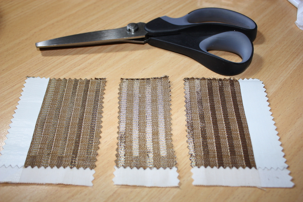
Cut a rectangle of fabric at least 20 x 10cm using pinking shears. (You may wish to make it up to a few centimeters bigger in each dimension slightly bigger if you want a bigger bow).
If using the fabric samples, you'll need half a sample. Cut a 3 - 4 cm strip from the middle and then glue or sew the two sides back together. We do this because of the paper glued on the back of the fabric along the sides - it looks better if the two sides are symmetrical.
Fold the edges of the fabric down along the sides and sew or use small spots of glue to hold in place. You can use paper behind the fabric to give the bow more stiffness. Fold the bowtie into a tube and glue along the back. Cut 22cm of the organza stripe ribbon and overlay on the top of the fabric. Glue or sew the sides of the bowtie together.
Attach piezo buzzer and neopixel in the middle with hot glue.
Put the middle of the 1cm wide grosgrain ribbon in place at the back of the bowtie (it will fasten at the back of your neck). Fold the sides of the small strip under and wrap around the middle of everything. Hold in place with staples.
Staple bits of velcro on the ends of the ribbon so it will fit your neck.
Use hot glue or sewing thread to attach NodeMCU board to the back of the bowtie.
After programming the board, attach the battery holder. You can hide this in a pocket or on your shoulder under your shirt.
All up, I put together 124 kits, one for every attendee at CampJS VI:
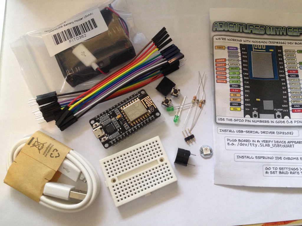
Here are pages from the handout from the session:
Note:
Espruino for ESP8266 is under active development, so some of these code samples may need tweaking to work with the latest version.